20 December 2009

Shack 2.0 Project: Second Part

Well, once workers were gone, I started working on the shack. I have put a new WEB page to document these works:

EB5AGV's Shack 2.0: Second Part

Here you have one picture of the current looks. Of course, still a work in progress:


73 JOSE EB5AGV

16 October 2009

Shack 2.0 Project

INITIAL CONDITION (1/OCT/2009)


UPDATED PICTURE (6/NOV/2009)


UPDATED PICTURE (13/NOV/2009)


Well, I am now in the middle of the shack rework!

I have put a new page in my WEB at:

EB5AGV's Shack 2.0 Project

I will update it frequently, so keep connected!

73 JOSE EB5AGV

12 August 2009

New addition to my RF lab: HP-8566A

Well, it has been (and continues to be) a big deal to have it working, but here you have my last addition to my RF lab: a 100Hz-22GHz HP-8566A Spectrum Analyzer


You can read about the repair and see plenty of pictures of the process at:

EB5AGV's Workbench: HP-8566A repair

Best regards,

JOSE

19 June 2009

Ten-Tec Paragon


I own a number of radio rigs from lots of different manufacturers (Yaesu, Kenwood, Icom, JRC, Drake, Collins, ...) but, until yesterday, I had no Ten-Tec in my collection. So my new Paragon is for me, besides a new toy, my very first Ten-Tec. I have fixed several Ten-Tecs over the years but I had none of my own.

This unit arrived in pretty good shape, with only some light dirt on it. I bought it as unworking in AM mode and generating extrange sounds at low frequencies. Obviously, I suspected of PLL problems as they are well documented all over the WEB... Well, I have not found yet any obvious problem with the rig in both aspects!. So I guess there could be an intermittent fault waiting to develop again.

Unit arrived with original User Manual (nice one, more like a Service Manual) and a non-original hand mike (which seems to be wired wrongly). It has an optional FM module, but no RS-232 module and no extra filters. Here you have some internal pics:


Only sign of previous repair I have located so far (I have not yet opened lower inner cover) is around the backup battery charging (I guess) circuit. BTW, battery holds a charge but memory and RTC are reset when power is out. So something is wrong here:


Despite the inclusion of the original Giehl EPROM manual in the back of the User Manual, this unit has an standard Ten-Tec EPROM on it, version 3.9:


I wonder if someone would sell me a Giehl EPROM...

I need to check the unit in detail but, so far, it seems to work pretty nicely.


UPDATE #1

I have just opened the inner bottom cover to check. There are good news!. Unit seems completely untouched. GREAT!!!

Here you have some pictures:


And now some more detailed pictures: this is from the PLL area. I have found that wiggling these connectors warbles the signal but this could be due to stray induced capacitances:

And this is the antenna discharge protection:


I will add more info as my work progresses.

73 JOSE EB5AGV

15 June 2009

What can we learn from AF-447 crash?

Well, I know this BLOG is not related to aviation but, taking into account that it seems most of the problems faced by the crew aboard the doomed AF-447 were electronic related, and this BLOG is about repairs, I am very interested in knowing what failed so badly to leave the tripulation completely in electronic darkness in that terrible night over the Atlantic.

It is clear for me that today commercial aviation needs electronics and that it would be impossible to fly without them. Fly By Wire is, IMHO, a big advantage over conventional controls, as it could be supervised by powerful computers aboard the plane. What we need is to know what failed in order to prevent it to fail again. And, at least, adding some extra info to the ACARS messages, as GPS location info, could help a lot finding the remains of the aircraft. Since I first read about the crash I wondered how, in this ultra-connected World, an airliner could be so, let's call it, off-line.

I am sure it will be possible to send real-time telemetry and audio data from the planes to a satellite based system, so the equivalent to the black boxes could be out of the plane and immediately available after a crash. And, even better, you could have an expert system analyzing all info so perhaps it could prevent, with some more anticipation, a large failure as the one which presumably generated the fatal end of Air France 447 flight.

Of course, this would cost money. Yes, I know. But how much would it cost to insurers, Airbus and Air France this accident?. How can you value a human life?. Not counting the huge effort to locate the remains and black boxes, which would be easier if there was more information available right now.

228 souls have died in an horrible accident, caused by technical failures (of course, triggered by powerful Nature forces). All what can be done to prevent other similar accidents should be done. We need to improve data communication with aircraft. It is a no brainer to have backup copies far from the computers which generate the data. So the same should be applied to aircraft data. We have the ways to do it and it is only a matter of work and money, both of them available to human beings.

Titanic was also unsinkable and now it rests in the deep sea. We know now that the Airbus 300 is not perfect and can be broken down. So we need to improve them (as all other airliners), as we did with big ships. And, for this, information is crucial.

RIP all 228 souls aboard AF-447. Your death will be sure a trigger for safer flights.

23 May 2009

Some news

Well, after long time without any update, I want to comment that I am very busy trying to get my shack upgraded, which will mean adding a new area, roughly similar to what I have now, so I can sepparate radio from lab. I will post pictures of the project as it evolves :-)

73 JOSE EB5AGV

17 January 2009

Yaesu FRG-8800 repair

Lately I spend most of my hobby time fixing rigs for other people. But this time I have fixed a rig for my collection. It is a Yaesu FRG-8800 receiver which suppossedly came with the VHF converter...

When I got it, I found a surprise. It is a heavily modified unit (called Broadcast Monitor Receiver 2) and there is NO VHF converter, but an extra module with balanced audio and IF output on its place, along some other PCBs and other internal mods. You can check what I am talking about here:

This is the company:

http://www.surreyelectronics.com/

This is the mod leaflet front page:

http://www.surreyelectronics.com/leaflets/Receiver2F.jpg

And this is the rear page:

http://www.surreyelectronics.com/leaflets/Receiver2R.jpg

Here you have some pictures:


Well, I knew it was in unworking condition and, really, it didn't work on arrival. No surprise here. I took the covers out to find some oxide in metal cans but mostly a clean receiver. This is the top side:


I polished the cans, dusted it out and started troubleshooting.

AM sort of worked but SSB was completely deaf. While turning the unit to check lower side, I heard some noise inside... and it was a lose piece of PCB!!!. I found it was a PCB corner and it had a trace on it... could this be the cause of the SSB deafness?. I fixed it by glueing and bridging it:


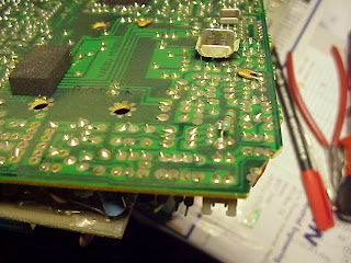
So I put back the PCB, hoping for the best... and no, it was WORSE!!!. Now AM was received faintly and SSB needed about 0.2V to be heard. So I went back to head scratching until I found that pulling the PCB a bit generated some better reception. So I decided to completely remove it:


I took some detailed pictures of the added PCBs:


As you can see, there are a couple IF filters in one PCB, a couple relays in another one and, I guess, a new detector on the third. The mods seem somewhat complex; I guess they are worth more than I have paid for the unit :-)

Looking closely I located the problem. There was another crack in a PCB corner.


I fixed it as follows, scrapping and adding some wire and solder on each crack:


Putting the PCB back got me a pretty hot working receiver :-)!!!. Here you have a very small video (sorry about the lousy quality):


So I decided it was time to clean the unit, removing knobs to clean them sepparately. I also replaced the four display light bulbs, as there was one bad, one dim and two with too much brightness. I put four new lamps.

Here you have some pictures of the cleaned unit, ready for alignment:


Alignment was mostly OK, just some Hertzs out in some oscillators. I used my GPS reference to be sure alignment was done OK.

And this is the result: a perfectly working receiver:


Success!!!