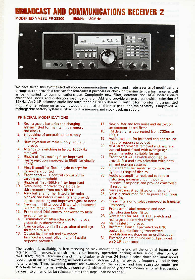
When I got it, I found a surprise. It is a heavily modified unit (called Broadcast Monitor Receiver 2) and there is NO VHF converter, but an extra module with balanced audio and IF output on its place, along some other PCBs and other internal mods. You can check what I am talking about here:
This is the company:
http://www.surreyelectronics.com/
This is the mod leaflet front page:
http://www.surreyelectronics.com/leaflets/Receiver2F.jpg
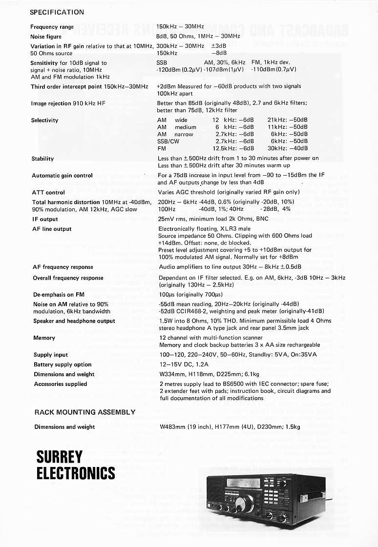
And this is the rear page:
http://www.surreyelectronics.com/leaflets/Receiver2R.jpg
Here you have some pictures:


Well, I knew it was in unworking condition and, really, it didn't work on arrival. No surprise here. I took the covers out to find some oxide in metal cans but mostly a clean receiver. This is the top side:

I polished the cans, dusted it out and started troubleshooting.
AM sort of worked but SSB was completely deaf. While turning the unit to check lower side, I heard some noise inside... and it was a lose piece of PCB!!!. I found it was a PCB corner and it had a trace on it... could this be the cause of the SSB deafness?. I fixed it by glueing and bridging it:


So I put back the PCB, hoping for the best... and no, it was WORSE!!!. Now AM was received faintly and SSB needed about 0.2V to be heard. So I went back to head scratching until I found that pulling the PCB a bit generated some better reception. So I decided to completely remove it:

I took some detailed pictures of the added PCBs:


As you can see, there are a couple IF filters in one PCB, a couple relays in another one and, I guess, a new detector on the third. The mods seem somewhat complex; I guess they are worth more than I have paid for the unit :-)
Looking closely I located the problem. There was another crack in a PCB corner.

I fixed it as follows, scrapping and adding some wire and solder on each crack:


Putting the PCB back got me a pretty hot working receiver :-)!!!. Here you have a very small video (sorry about the lousy quality):
So I decided it was time to clean the unit, removing knobs to clean them sepparately. I also replaced the four display light bulbs, as there was one bad, one dim and two with too much brightness. I put four new lamps.
Here you have some pictures of the cleaned unit, ready for alignment:


Alignment was mostly OK, just some Hertzs out in some oscillators. I used my GPS reference to be sure alignment was done OK.
And this is the result: a perfectly working receiver:

Success!!!